√無料でダウンロード! ic 7432 truth table 197239-Ic 7432 truth table
Revised March 00 DM74LS32 Quad 2Input OR Gate General Description This device contains four independent gates each of which performs the logic OR function Ordering Code Devices also available in Tape and Reel Specify by appending the suffix letter "X" to the ordering codeIC XNOR GATE · IC 7402 comes up in multiple packages with 14 pins and 2 inputs 4NOR gates NOR gate is designed with advanced technology based on silicon IC 74LS02 internal structure based on CMOS technology In IC all gates come up with buffered output and it has the ability to provide noise immunity to drive LSTTL Loads
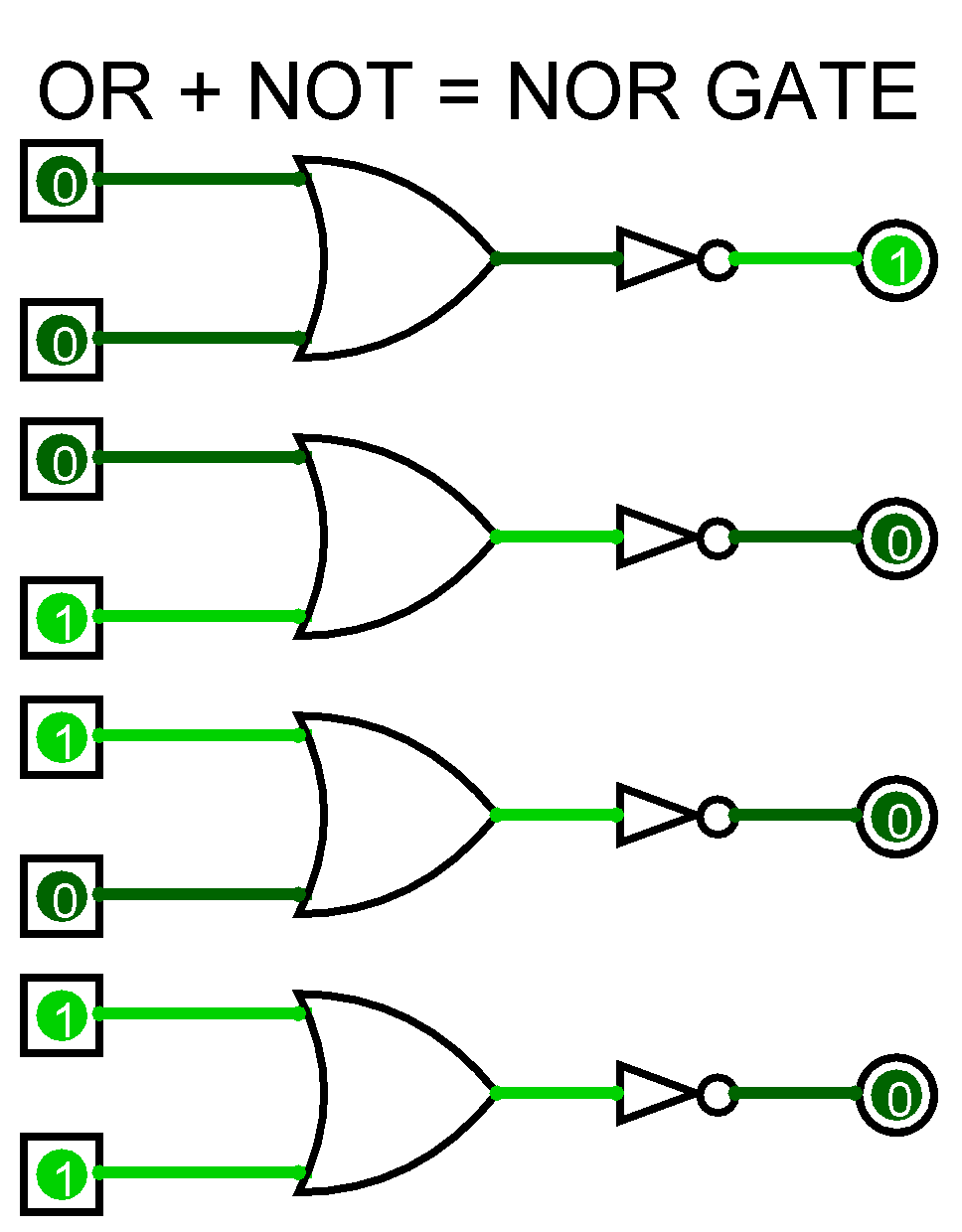
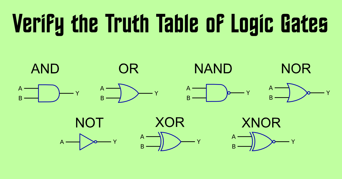
Basics Of Logic Gates With Truth Table Ahirlabs
Ic 7432 truth table
Ic 7432 truth table- · Explain Logic OR Gate and Its operation with Truth Table from electronicspostcom 7432 or gate datasheet pdf provided by datasheetspdfcom datasheet pdf search for 7432 Pin diagram of ic 7432 given here • bits of the binary number are or gate • it can have two or more inputs and performs known as logical additionThe 74LS32 is a Dual Input OR Gate with Quad package It contains four independent gates each of which performs the logic OR function Each gate has two inputs that's why it is named Quad 2Input OR Gate Logic level gates like 74LS32 and flipflops play a vital role in digital electronics


Q Tbn And9gctufyx5joyoihqml30nmesm Fu23bhszo8 P6dqs4fv8i7ng5zm Usqp Cau
· We have designed XOR and XNOR gate by using different suitable combinations of AND OR & NOT gate As we have also verified the truth tables of XOR & XNOR gate, we can deduce some main points from this The total OR & AND logic gates in IC's 7432 & 7408 respectively are 4, and 6 NOT logic gates in IC 7404IC 7408 AND GATE;Logic gates are the main elements of digital system To understand the digital system or circuit we should understand the logic gates and it's input/output b
AND gate 7408 TRUTH TABLE B A out OR GATE IC 7432 The OR gate is a digital And gate 7408 truth table b a out or gate ic 7432 the School Algoma University;IC 7400 NAND GATE; · From the truth table, the multiplexer can be constructed using AND gates, NOT gates and OR gates Since there are two select pins and data from each input is routed through one AND gate, 3input AND gates are required for the circuit Here, for constructing the multiplexer circuit, 7404 IC for NOT gate, 7411 IC for AND gate and 7432 IC for OR
Fig 65 TFlipFlop using JK FlipFlop & its Truth table Symbol Procedure Connect the NOT gate using digital IC's as shown in the figure 51 Use 5V for logic l and 0V for logic 0 Feed the logic signals 0 or l from the logic input switches at the inputs A & B Monitor the output using LED indicators and verify its truth tableIC 7432 OR GATE;IC Pin Diagram, Truth Table, Logical Circuit, Applications Digital Electronics , Electronics , Logic Gate IC IC is a Logical Decoder IC It also has a demultiplexing facility The IC is available in the market with the name of 74LS138 It is a 3 to 8 decoder IC The internal circuit of this IC is made of highspeed Schottky


Solved Experiment 3 Basic Logic Gates Components Needed 7408 Ic Quad Two Input And Gate 7432 Ic Quad Two Input Or Gate 7404 Ic Hex Inverter Not Course Hero


Or Gate Circuit Diagram Using Ic 74ls32
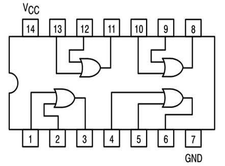
· ic ttl 7432 IC TTL adalah IC yang banyak digunakan dalam rangkaian digital karena menggunakan sumber tegangan (VS) antara 4,75 Volt sampai 5,25 Volt Komponen pembangun IC TTL(transistortransistor logic) adalah sesuai dengan namanya IC ini berisi beberapa transistor yang digabungkan sehingga membentuk dua keadaan (ON/FF)Aim To design, Implement and verify the truth table of adder using logic gates Apparatus Required SI No COMPONENT SPECIFICATION QTY 1 AND GATE IC 7408 1 2 OR GATE IC 7432 1 3 XOR GATE IC 7486 1 4 DIGITAL IC TRAINER KIT1 5 PATCH CORDIC 7432 is a logic gate IC which consist of four OR Gates The OR gate performs logical OR operation The OR gates come in form of DIP package ICs Each gate has three terminal two inputs and one output The ICs are made by CMOS, TTL technology


Ic 7400 Pin Configuration Circuit Specifications And Its Applications


Introduction To Logic Gates Or Gate
Verification and interpretation of truth tables for AND, OR, NOT, NAND, NOR Exclusive OR (EXOR), Exclusive NOR (EXNOR) Gates Apparatus Logic trainer kit, logic gates / ICs, wires Theory Logic gates are electronic circuits which perform logical functions on one or more inputs to produce one output There are seven logic gates When all the input combinations of a logic gate areProcedure Connect the NOT gate using digital IC's as shown in the figure 51 Use 5V for logic 1 and 0V for logic 0 Feed the logic signals 0 or 1 from the logic input switches at the inputs A & B Monitor the output using LED indicators and verify its truth table Repeat step l to 4 for all the remaining gatesThe output voltage of the IC on the pin Y will be equal to the operating voltage of the IC As per the OR gate truth table, when either one or both the input of the Gate is high the output will be high The truth table of the OR gate is given as A 1 x IC 7432 Quad2Input OR Gate Specification


Engineering Practicals Study Of Or Gate And Verification Of Output With Truth Table
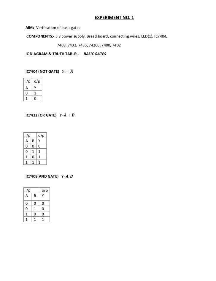


Experimentdsd 1
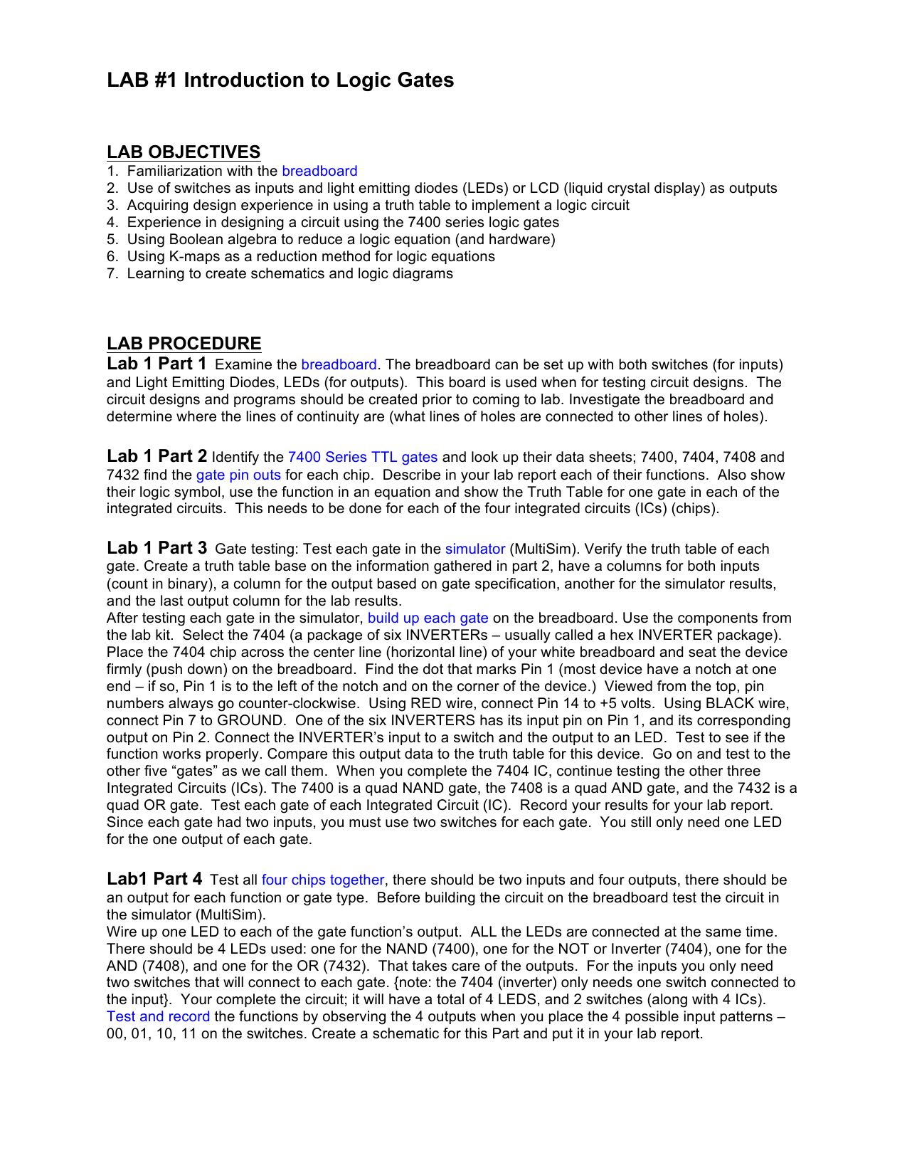
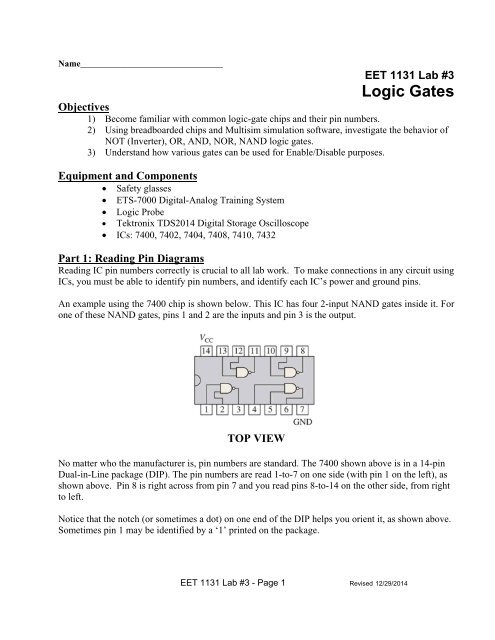
IC 7486 XOR GATE;Truth Tables and Gates Gates ICs used 7404, 7410, 7411, 7427, 7432 The following are exercises demonstrate the use of a protoboard for wiring integrated circuits (ICs) Each exercise shall be demonstrated to the instructor and initialled by him/her to receive creditCompare this output data to the truth table for this device Go on and test to the other five "gates" as we call them When you complete the 7404 IC, continue testing the other three Integrated Circuits (ICs) The 7400 is a quad NAND gate, the 7408 is a quad AND gate, and the 7432 is a quad OR gate Test each gate of each Integrated Circuit (IC)


Or Gate What Is It Working Principle Circuit Diagram Electrical4u


7432 74hc32 74ls32 Ic Quad 2 Input Or Gate
The Symbol and truth table of OR gate is shown in the figure 5 IC 7432 is used for OR operation it contains four, 2 input OR gates Figure 5 symbol and truth table of OR gate · Logic OR Gate Tutorial An OR gate is a digital logic gate circuit that perform logic OR operation The logic OR gate operation is when any of the inputs are high or "1" the output will be high or "1", otherwise output is low "0" when all inputs are low "0" The logical symbol of two inputs OR gate is shown below The Boolean expression of digital logic OR gate is the logical2 Answers2 The cascading inputs come from the outputs of another 7485 If you wish to create a 16 bit magnitude comparator, the other 7485 connects to the least significant byte (LSB) As for the last line of the truth table, the outputs indicate that the 'A' inputs are simultaneously greater and less than the 'B' inputs, which is contradictory


1


7432 Datasheet
Uploaded By giridharan6251 Pages 44 This preview shows page 23 30 out of 44 pagesTruth Table IC 7432 It is a quad two input OR gate All four OR gates may be used independently On any gate if either of the input is 'High' then the Output is 'High' When both the inputs are 'Low' then the output is 'Low' Pin Diagram Truth Table IC 7486 It is a quad two input ExOR gate All four ExclusiveOR gates may be used independentlyThe standard 4000 series CMOS IC is the 4071, which includes four independent twoinput OR gates The TTL device is the 7432 The TTL device is the 7432 There are many offshoots of the original 7432 OR gate, all having the same pinout but different internal architecture, allowing them to operate in different voltage ranges and/or at higher speeds


Or Gate Wikipedia


Logic Gates Introduction All Technology Subjects
IC 7402 NOR GATE;If or gate ic 7432 pin diagram have a power supply capable of 10 amps and your circuit only needs 5 amps, then 5 amps is all that it will pull Power P is voltage multiplied by current ALL GATES IC Number, symbols, Truth Table with explanation and Pin Diagrams19 ExptNo4 HALF SUBTRACTOR AND FULL SUBTRACTOR Aim To design and verify the truth table of the half subtractor & full subtractor circuits Apparatus required SlNo Name of the Apparatus Range Quantity 1 Digital IC trainer kit 1 2 AND gate IC 7408 1 3 OR gate IC 7432 1 4 NOT gate IC 7404 1 5 EXOR gate IC 7486 1 6


Remote Triggered Digital System Laboratory


Jecassam Ac In Wp Content Uploads 18 10 5digital Signal Logic Design Lab Pdf
Course Title ECE MISC; · Truth tables for each individual gate can be paused for better observation and can be skipped for saving time There is feasibility of reproducing the previous stage (for reentering the data) without resetting the device 16MHz of processing speed makes the time response of this IC tester pretty good · The circuit can easily built using a 7432 OR gate IC I have built my encoder circuit over a breadboard as shown below The four input lines (I0, I1, I2 and I3) are provided by the four push buttons, when the button is pressed it links 5V to the pin making it logic 1 and when the button is not pressed the pin is held to ground through a 10k


Recent Phd Result Integrated Circuit Hardware Description Language


Csc270 Lab 3
· 74LS32 IC – Quad 2Input OR Gate IC (7432 IC) You can also call us at or send us a message through our Facebook page For all your product inquiries, send us a message on our Contact Page with the Product Inquiry subject The truth table for the OR gate is shown below · AIM To Study and Verify the Truth Table of Logic Gates LEARNING OBJECTIVE Identify various ICs and their specification COMPONENTS REQUIRED Logic gates (IC) trainer kit Connecting patch chords IC IC 7404 NOT GATE; · As we have verified the truth tables of OR, AND & NOT gate, we can deduce some main points from this The total OR and AND logic gates in IC's 7432 & 7408 respectively are 4, and 6 NOT logic gates in IC 7404 The logic gate whose all output entries are 1 except the one for which both of the inputs are 0, is known to be as OR gate


Verification Of Truth Tables Of Logic Gates Using Integrated Circuits Physics Practical Experiment


Forum Easyeda An Easier Electronic Circuit Design Experience Easyeda
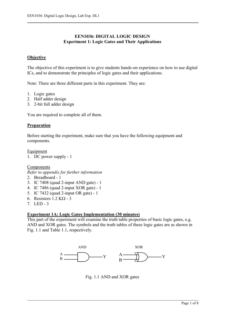
Introduction to digital electronics lab nomenclature of digital ICs, specifications, study of the data sheet, concept of Vcc and ground, verification of the truth tables of logic gates using TTL ICs Apparatus Required Digital lab kit, single strand wires, breadboard, TTL IC's Gates IC NO AND 7408 OR 7432 NAND 7400 NOR 7402 NOT 7404Given a Truth table to derive the Boolean expressions and build the logic circuit to realize it COMPONENTS REQUIRED IC 7400, IC 7408, IC 7432, IC 7406, IC 7402, Patch Cords & IC Trainer Kit THEORY Canonical Forms (Normal Forms) Any Boolean function can be written in disjunctiveIC 7432 Connecting Wires LED with resistors PIN DIAGRAM G PIN DIAGRAM OF IC 7432 QUAD 2 INPUTS OR GATE THEORY PROCEDURE Connect the circuit as shown in the circuit diagram Before switching ON power Supply, make sure that the connections are correct Apply the input logic as per Truth table in terms of 5 volts for state1 and 0 volts


Digital Technique Handout 1
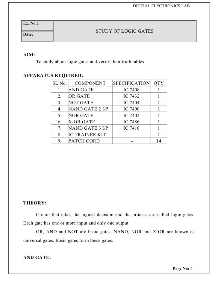


De Lab Manual
/06/15 · The most commonly (widely) used OR gate ICs are listed below TTL Logic OR Gates 74LS32 Quad 2input CMOS Logic OR Gates CD4071 Quad 2input CD4075 Triple 3input CD4072 Dual 4input Hex 2input OR drivers 742 All available OR logic gate ICs are tabulated below 7432 Quad 2input OR Gate IC · Hello guys, welcome back to my blog In this article, I will discuss the different types of logic gates in digital electronics, IC numbers of logic gates, truth table, diagram, working of logic gates, etc If you need an article on some other topics then comment us below in the comment boxThere was a problem previewing EXP1pdf Retrying
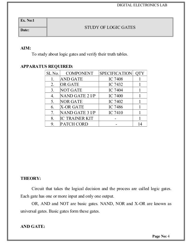


Digital Electronics Lab


Logic Gate Truth Tables Online Version Objective Chegg Com
7432 Datasheet, PDF Includes HDMI, HDMI to DVID, MicroCross DVID and DVII, DisplayPort, IEEE, USB Type A and B, USB OTG (OntheGo) miniB, Micro USBB MicroCross™ DVII Digital/Analog Visual Interface, PCB Receptacle, Through HoleRight Angle, 234mm (092") PC Tail Length, 29 Circuits, Lead FreeIt will give high if either all or any of the input is high 7432 has 4 OR gates of 2 inputs in 1 package The internal gates in the ICs are made of Schottky Transistor of low power OR gate finds a Maximum of 2 binary digits Boolean Expression Y = A B Truth Table/07/17 · Acting as a response analyzer, the MATLAB verifies each and every possible outcome according to the truth table of a particular IC 74xx series ICs that can be tested by this project are 7400, 7402, 7404, 7408, 7432 and 7486 Truth tables for these ICs are shown on the next page Software 1 Arduino IDE 165 is used to program the Arduino


Experiment No 10
.png)


74ls32 Or Gate Datasheet Pinout Equivalent Specs
· 7432 IC – The 7432 IC has quad 2input OR gates The IC has the following pin configuration – Fig 9 Table listing pin configuration of 7432 IC The IC has the following Pin Diagram – Fig 10 Pin Diagram of 7432 IC The IC requires a supply voltage of 5V which can be tolerated up to 7V7432 Datasheet (PDF) Fairchild Semiconductor Part No 7432 Download 7432 Click to view File Size 59 Kbytes PageThread / Post s Title trignometric table and logarithmi table Page Link trignometric table and logarithmi table Posted By Anil J Created at Sunday 16th of April 17 PM how to calculate log from log table, system design for time table generator, e r diagram for time table generator management system project, real time project hourly time table using ic2 protocol,


Verification Of Truth Tables Of Logic Gates Using Integrated Circuits Physics Practical Experiment


De Lab Logic Gate Digital Electronics
The AND gate output will be in high state only when all the inputs are in high state 7408 is a Quad 2 input AND gate OR gate It performs logical addition Its output become high if any of the inputs is in logic high 7432 is a Quad 2 input OR gate
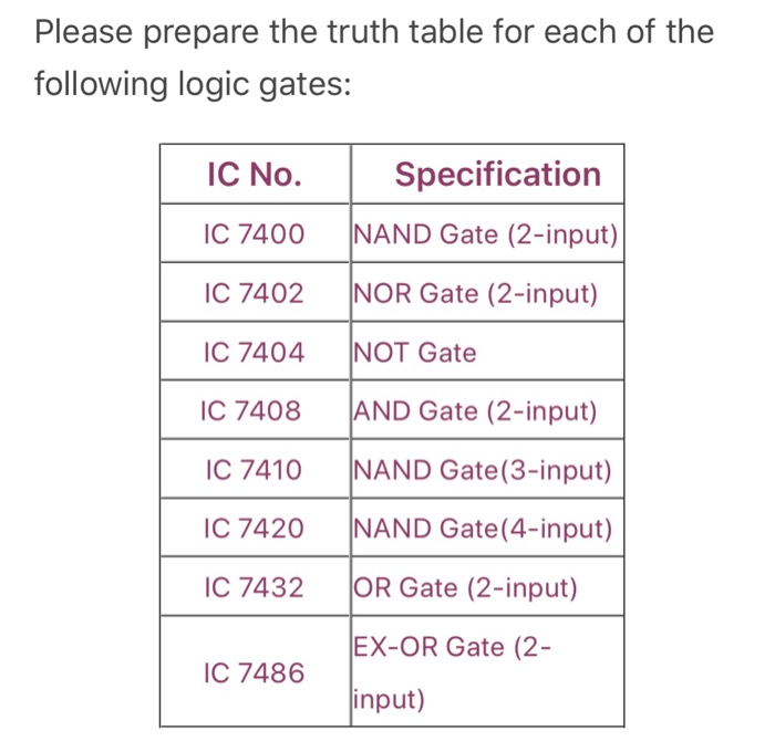


Please Prepare The Truth Table For Each Of The Chegg Com


Lab Manual Digital Electronics Amittal


74ls32 Or Gate Truth Table Example Youtube


Basics Of Logic Gates With Truth Table Ahirlabs


Ic 7432 Pin Diagram Circuit Design Datasheet Application Etechnog


Ic 7432 Quad 2 Input Or Gate Solic Stores


Nor Gate Or 7432 Not 7404 Youtube


Verification Of Truth Tables Of Logic Gates Using Integrated Circuits Physics Practical Experiment


Lab Manual Digital Electronics Amittal


Digital Technique Handout 8


Q Tbn And9gctufyx5joyoihqml30nmesm Fu23bhszo8 P6dqs4fv8i7ng5zm Usqp Cau


Simple One And Two Input Logic Gates Truth Tables And Function Tables Based Upon 0 5 V Ppt Download


Ic 7432 Pin Diagram Circuit Design Datasheet Application Etechnog


Lab Manual Digital Electronics Amittal


Q Tbn And9gctwfpfbf0ekbpk63pq8e9jykh7z6h5ez0q Radxdsehiwcusz Usqp Cau


Dblocks


Logic Or Gate Tutorial With Logic Or Gate Truth Table
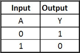


Get Started With Not Gate Ic 7400 Series Tutorial


Lab 1 Introduction To Logic Gates Manualzz


Logic Gate Ic S Concise Information And Various Applications Of Logic Gate Ic S
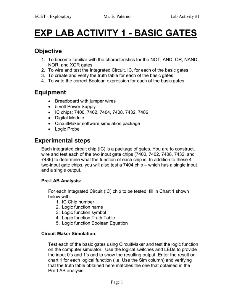


1 Basic Logic Functions Lab Activities Manualzz


Basics Of Logic Gates With Truth Table Ahirlabs


Logic Gates


Ic 7432 Quad 2 Input Or Gate Solic Stores


The Basic Elements Of Digital Circuits Mosfet Gate And The Logic


M1vgine13ql 6m


Basic Logic Gates Logic Gate Computer Engineering


Een1036 Digital Logic Design


Or Gate Circuit Diagram Using Ic 74ls32


Logic Ics Or Gate Logic Ics How To Use Them And Or Not or Nand Gate


Solved Experiment 3 Basic Logic Gates Components Needed 7408 Ic Quad Two Input And Gate 7432 Ic Quad Two Input Or Gate 7404 Ic Hex Inverter Not Course Hero
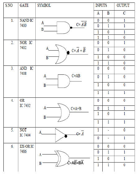


Digital Logic Gate Ics With Symbols And Truth Tables Bragitoff Com


Gate Ic Factoryforward
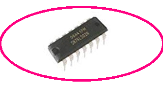


Ic 7432 Pin Diagram Circuit Design Datasheet Application Etechnog


Ic 7432 Truth Table Verification Using Dkt Digital Trainer Kit Youtube


Http Abirami Yolasite Com Resources De Record 2nd Pdf


Ex 1 Logic Gate Electronic Design
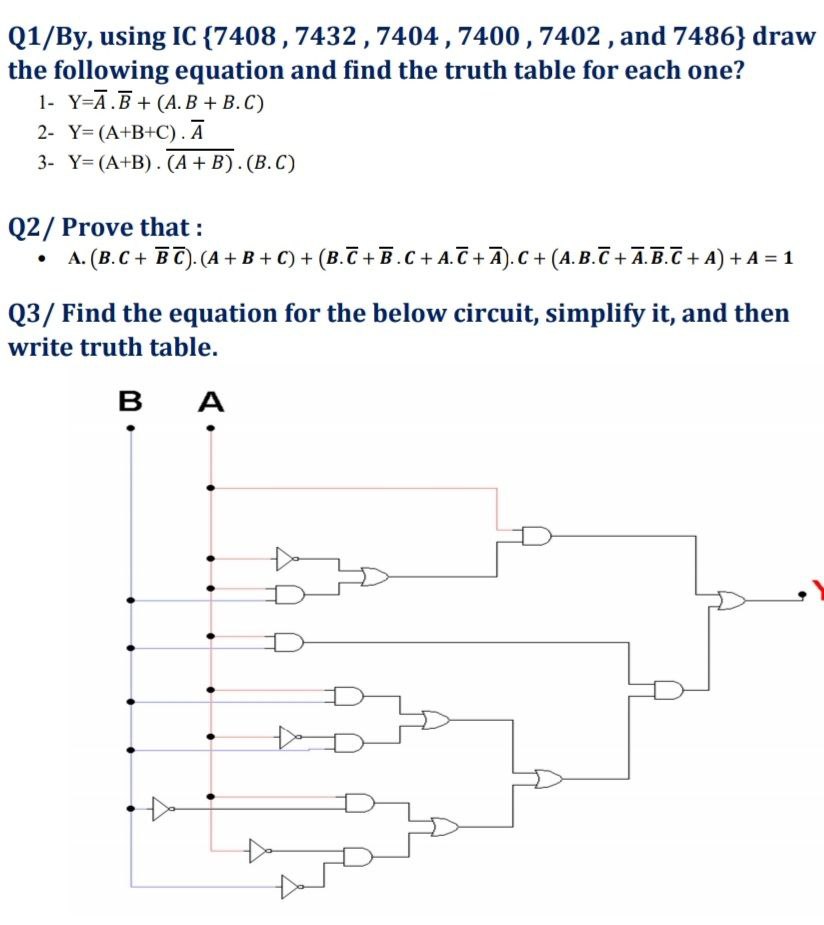


Answered Q1 By Using Ic 7408 7432 7404 7400 Bartleby
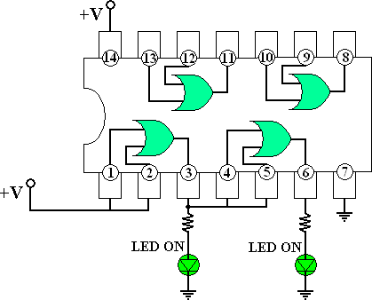


7432 Quad 2 Input Or Gate Integrated Circuit


Dblocks


Logic Gate Ic S Concise Information And Various Applications Of Logic Gate Ic S
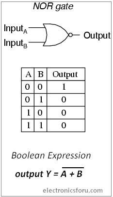


Get Started With Not Gate Ic 7400 Series Tutorial


Practical Electronics Ic 4071 Wikibooks Open Books For An Open World


Experiment No 2 Studocu


7432 Behaves Like An And Gate 7408 Behaves Like An Or Gate Electrical Engineering Stack Exchange


Http Abirami Yolasite Com Resources De Record 2nd Pdf


7432 Techwiki
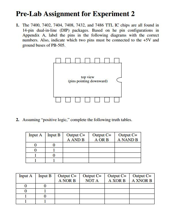


Pre Lab Assignment For Experiment 2 1 The 7400 Chegg Com


Lab Manual Digital Electronics Amittal


7432 Ic Quad 2 Input Or Gate


Digital Logic Gate Ics With Symbols And Truth Tables Bragitoff Com


Pdf Experiment 1 Basic Logic Gates Mohammed Altamimy Academia Edu


1


Logic Ics Or Gate Logic Ics How To Use Them And Or Not or Nand Gate
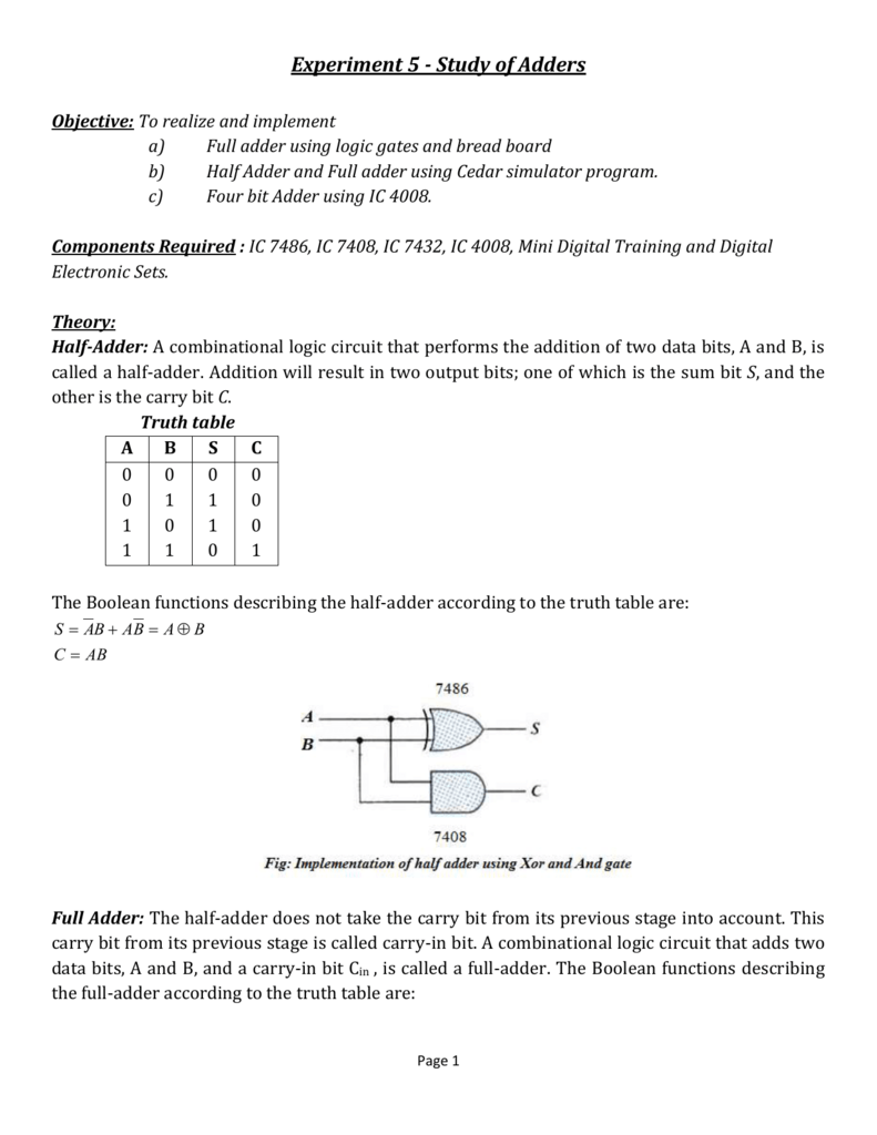


File
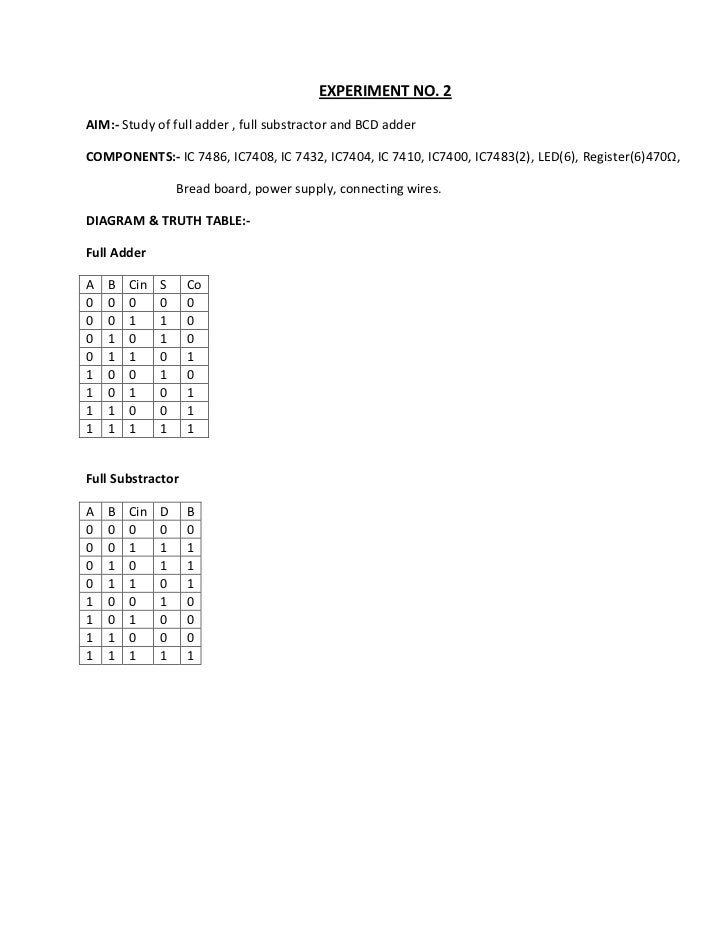


Experimentdsd 1


Logic Gate Ic S Concise Information And Various Applications Of Logic Gate Ic S


Or Gate Wikipedia


Doc Introduction To Logic Gates Divyesh Divakar Academia Edu
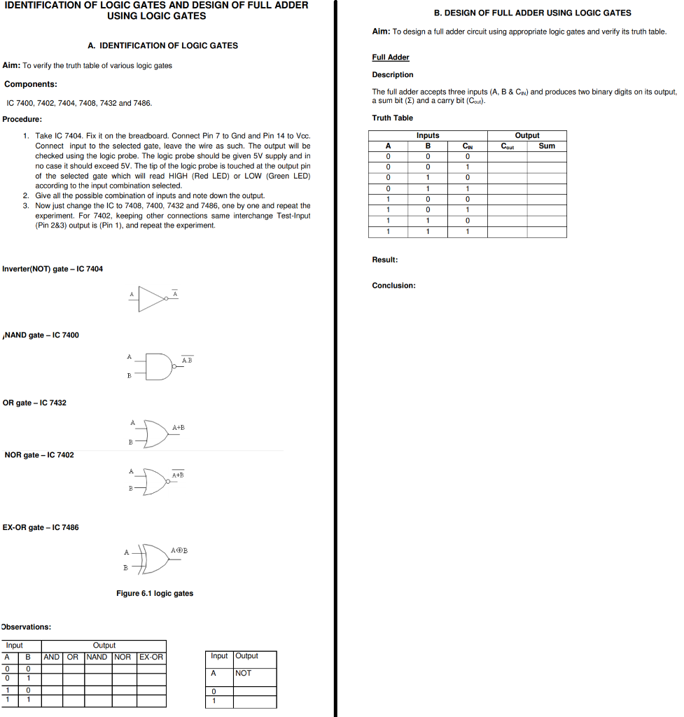


Solved Identification Of Logic Gates And Design Of Full A Chegg Com


Digital Electronics Circuit In Breadboard Or Logic Gate Ic 7432 And Truth Table Youtube


All Gates Ic Number Symbols Truth Table With Explanation And Pin Diagrams Youtube


Jecassam Ac In Wp Content Uploads 18 10 5digital Signal Logic Design Lab Pdf


Lekule Logical Or Gate


Sjce Ac In Wp Content Uploads 18 01 Dec Lab Manual 1st Aug 17 Pdf
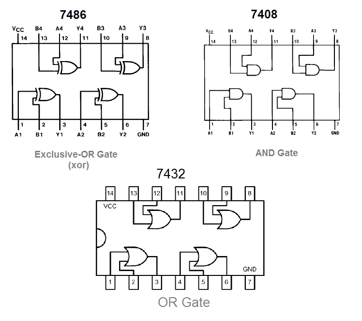


Full Adder Circuit Diagram


Lab 2 Logic Gates Boolean Algebra And Combinational Chegg Com


Digital Electronics Lab Report No 01 Logic Gate Digital Electronics


Sn74ls32 Ic 7432 Two Input Or Gate Youtube
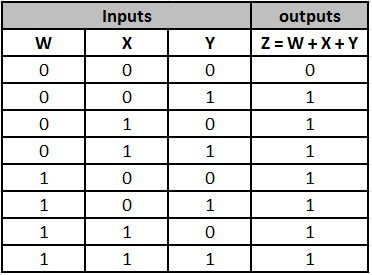


Digital Logic Or Gate


Ic 7432 Quad 2 Input Or Gate Solic Stores
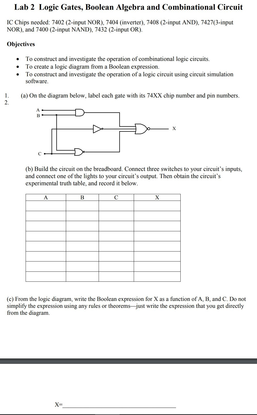


Lab 2 Logic Gates Boolean Algebra And Combinational Chegg Com


Study Of Logic Gates Pulse And Digital Circuits Lab Vikramlearning Com


Breadboard 2 Logic Multiple Gates Joe S Hobby Electronics


Introduction To Logic Gates May 18


74ls32 Or Gate Datasheet Pinout Equivalent Specs


Or Gate Making Verification Of Truth Table Using Ic 7432 Youtube


Logic Gate Truth Tables Online Version Objective Chegg Com


コメント
コメントを投稿